Engineering Reference: Industrial EV Charging Power Distribution
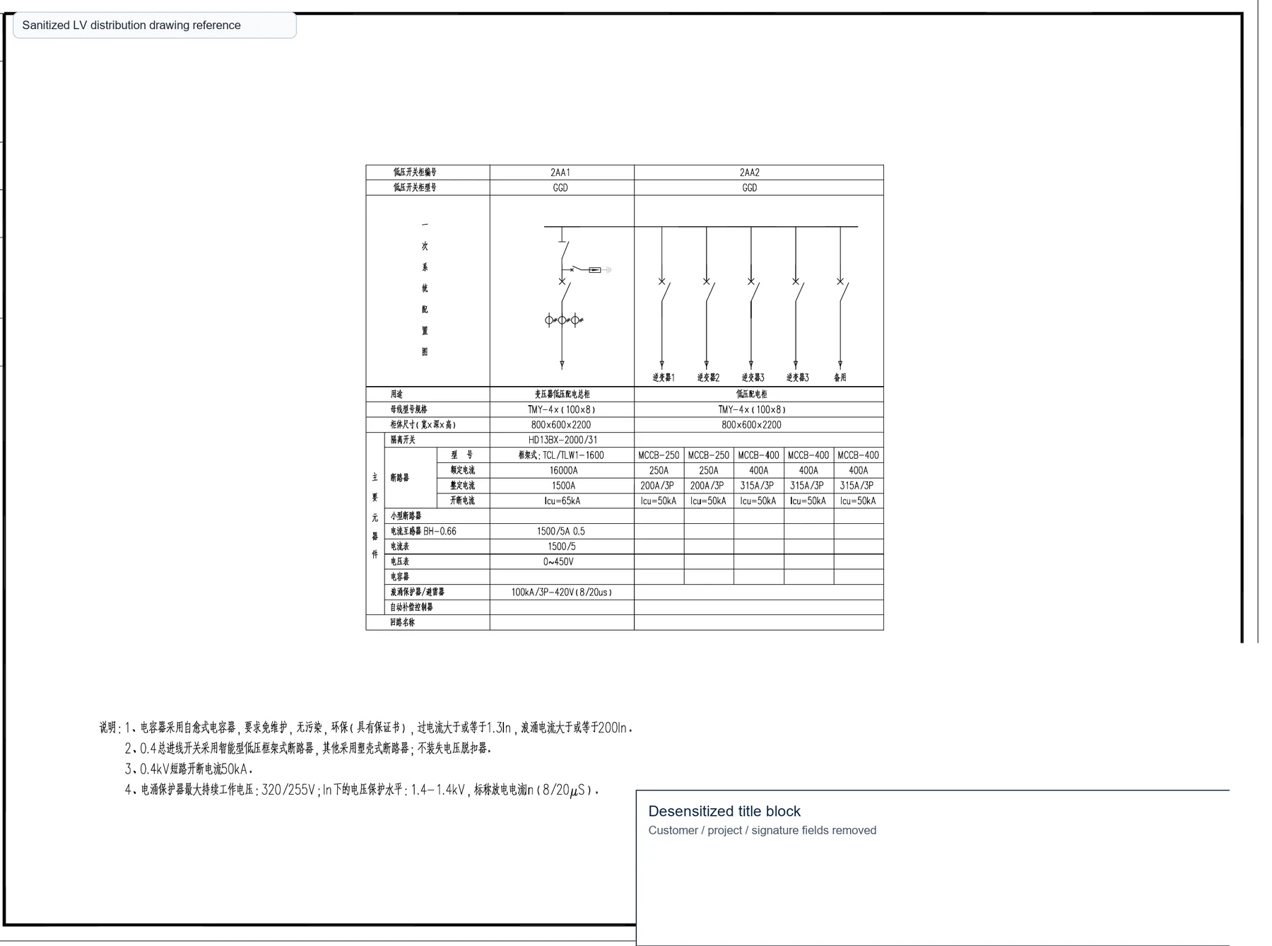
Engineering References are technical notes, not marketing pages. This reference explains the power distribution logic behind an industrial EV charging project using a sanitized technical drawing excerpt.
Search Intent
- industrial EV charging power distribution design
- transformer sizing for EV charging station
- LV switchgear for EV charger feeders
- EV charging station RFQ checklist
Design Objectives
Industrial EV charging projects typically require:
- Safe power distribution for multiple high-current charging feeders.
- Reliable continuous operation under variable charging demand.
- Future charging expansion without rebuilding the full distribution room.
- Maintainable low-voltage switchgear with clear feeder identification.
- Compliance with local utility, earthing, protection and IEC requirements.
Engineering Summary
An industrial charging project normally includes utility supply, transformer capacity planning, main LV switchgear, outgoing charger feeders, metering, protection and cable routing. The design should not only match the first installed chargers but also reserve space for future charging points.
The most important engineering question is not the number of chargers alone. It is the expected simultaneous charging demand, future expansion plan, transformer loading margin and feeder protection strategy.
Typical Engineering Workflow
- Site survey: confirm utility access, electrical room, cable route and charger locations.
- Load estimation: define charger rating, quantity and simultaneous charging factor.
- Transformer sizing: choose capacity with realistic demand and future expansion margin.
- MV/LV distribution: select transformer, LV main switchboard and feeder panel structure.
- Protection coordination: coordinate ACB/MCCB settings, leakage protection and upstream protection.
- Cable routing: confirm conductor size, laying method, voltage drop and installation route.
- Metering: define main metering, charger metering and communication requirements.
- Commissioning: test insulation, phase sequence, protection settings and charger load behavior.
System Architecture
A typical industrial EV charging power system can be arranged as:
- Medium-voltage incoming supply or existing site distribution source.
- Transformer or compact substation sized for charging demand.
- Main low-voltage switchgear with incoming ACB and metering.
- Outgoing feeder circuits for charger groups.
- Protection, earthing, surge protection and monitoring interfaces.
Equipment Selection
| Equipment | Typical Role | RFQ Information Needed |
|---|---|---|
| Oil-immersed transformer or SCB13 dry-type transformer | Supplies charging load from utility or site distribution voltage. | Charger total load, simultaneous factor, voltage, installation environment and expansion margin. |
| GCS LV switchgear | Main incoming, busbar and outgoing feeder distribution for chargers. | Rated current, breaker list, feeder quantity, busbar rating, communication and metering. |
| GGD distribution panel | Fixed LV feeder panel for simpler charging groups. | Feeder schedule, MCCB sizes, cable entry and installation layout. |
| Prefabricated substation | Outdoor transformer plus MV/LV distribution package where a compact station is required. | Transformer capacity, enclosure type, MV scheme, LV feeders and site environment. |
| Power cables | Connect transformer, switchgear and charging feeders. | Cable size, length, laying method, conductor material and voltage drop limit. |
Engineering Considerations
- Simultaneous charging: total installed charger power may be higher than actual operating demand, but assumptions must be agreed with the owner or EPC.
- Transformer margin: future charger expansion should be considered during first-stage sizing.
- Feeder protection: MCCB rating, leakage protection and selectivity should match charger characteristics.
- Voltage drop: long cable runs to charger groups can affect performance and cable size.
- Heat and ventilation: LV switchgear and transformer rooms need heat dissipation under high charging load.
- Metering: main metering and charger-level metering may both be required.
Common Engineering Mistakes
- Selecting transformer capacity without future charger expansion margin.
- Ignoring simultaneous charging factor and treating every charger as continuous full load.
- Undersizing feeder cables because cable length and laying method were not confirmed.
- Using insufficient short-circuit capacity for the main LV switchgear.
- No spare feeder positions for additional chargers.
- Leaving metering and communication requirements until after cabinet production.
Engineering Lessons
Industrial charging demand rarely stays constant. Planning spare transformer capacity and additional feeder positions during the first design phase usually reduces future expansion cost.
Another lesson is that charger power rating is only one part of the design. The electrical drawing must also show feeder grouping, cable route, switchgear capacity, protection philosophy and operating assumptions.
Design Verification Checklist
- Charger quantity and rated power confirmed.
- Simultaneous charging factor confirmed.
- Utility voltage and transformer voltage confirmed.
- Transformer capacity and expansion margin confirmed.
- LV switchgear busbar rating and incoming breaker confirmed.
- Outgoing feeder schedule and cable route confirmed.
- Metering and communication requirements confirmed.
- Earthing and leakage protection requirements confirmed.
Applicable Products
- SCB13 dry-type transformer
- S22-M oil-immersed transformer
- YB prefabricated substation
- GCS low-voltage switchgear
- Power cables and accessories
FAQ
What transformer size is suitable for an EV charging station?
The transformer size depends on charger quantity, charger rating, simultaneous charging factor, voltage, future expansion and utility requirements. It should not be selected only by summing nameplate charger power.
How is simultaneous charging calculated?
The factor depends on operating pattern, charger management strategy and customer requirement. Industrial fleets may have a different demand pattern from public highway charging stations.
When should a prefabricated substation be used?
A prefabricated substation is useful when the site needs an outdoor package including transformer, MV section, LV distribution and enclosure with faster installation.
How much spare capacity should be reserved?
Reserve capacity depends on planned charger expansion, utility limits and budget. It is often more economical to reserve busbar capacity and feeder space during the first stage.
RFQ Checklist
If the electrical drawing is not finalized, send the available load list and site information. The engineering team can assist with preliminary equipment selection before quotation.
- Charger quantity and power rating
- Site voltage and frequency
- Expected simultaneous charging factor
- Transformer installation type: indoor, outdoor or package substation
- LV feeder quantity and breaker preference
- Cable route length and laying method
- Future expansion plan
Engineering Reference Download
For charging infrastructure procurement, request a project-specific engineering reference instead of using an unrelated drawing. ZY POWER can review the available load list and prepare a transformer and switchgear configuration for quotation.
Download This Guide as PDF
Save this technical guide for offline reference. Includes all tables, specifications, and contact information.
Related Articles
Engineering Reference: MV/LV Switchgear Design
A technical reference for MV/LV switchgear design, feeder planning, single-line diagrams, equipment selection and RFQ preparation.
Engineering Reference: Distributed Solar PV Electrical Design
A technical reference for distributed solar PV electrical design, inverter grouping, transformer selection, MV switchgear, metering and RFQ preparation.