Engineering Reference: MV/LV Switchgear Design
Engineering References are technical notes, not marketing pages. This reference uses a sanitized internal drawing excerpt to explain how MV/LV switchgear design information is normally organized for procurement and engineering review.
Search Intent
- MV/LV switchgear single-line diagram reference
- low voltage switchboard feeder schedule
- switchgear RFQ information checklist
- KYN28A and GCS switchgear design reference
Design Objectives
A practical MV/LV switchgear design should achieve the following objectives before equipment procurement starts:
- Reliable power distribution from medium-voltage incoming supply to low-voltage outgoing feeders.
- Safe operation through correct short-circuit rating, earthing, interlocking and protection coordination.
- Maintainable cabinet arrangement with clear access, cable entry direction and compartment planning.
- Future expansion allowance through spare feeders, busbar capacity and cabinet space.
- Compliance with applicable IEC, utility and project specification requirements.
- Clear RFQ information so transformer, switchgear and protection devices can be selected without repeated clarification.
Engineering Summary
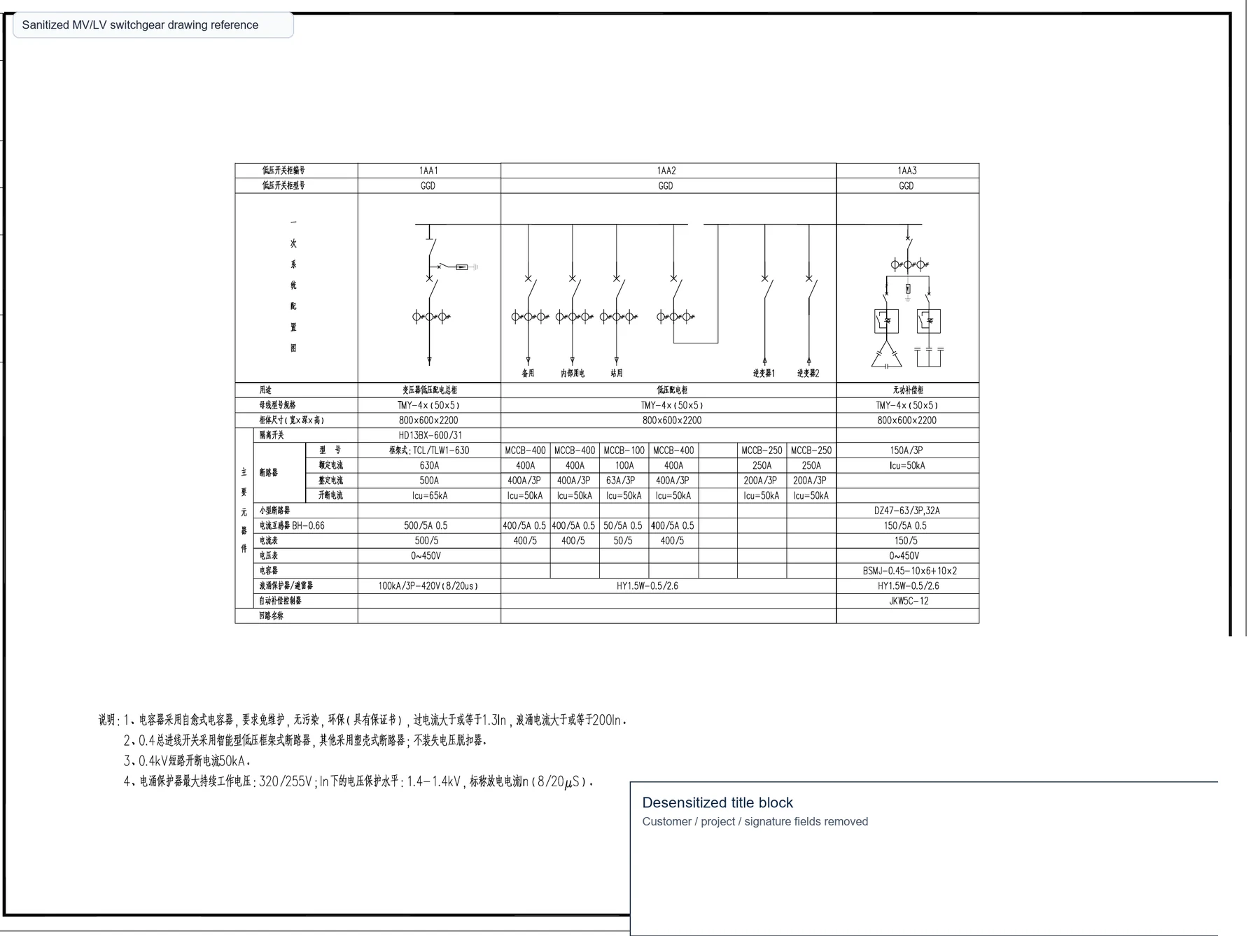
This reference illustrates how a power distribution drawing can connect incoming medium-voltage supply, transformer capacity, low-voltage main distribution and outgoing feeder circuits into one procurement-ready structure. It is intended for EPC teams, project engineers and buyers preparing a switchgear inquiry.
The public drawing image is not a complete project drawing. It is a cropped technical excerpt showing the useful engineering logic while removing customer-identifiable information.
Typical Engineering Workflow
- Requirements: confirm utility voltage, load list, operating environment and project scope.
- Load calculation: estimate transformer capacity, diversity factor and future margin.
- Single-line diagram: define incoming, transformer, busbar, bus tie and outgoing feeder logic.
- Switchgear selection: select MV switchgear, LV switchboard, breaker frame, drawer/fixed type and metering.
- Protection coordination: match relay, ACB, MCCB, CT and downstream protection settings.
- Factory production: freeze approved drawings, cabinet dimensions, busbar rating and cable access.
- Testing: perform routine tests and verify wiring, interlocks, insulation and functional operation.
- Delivery: pack cabinets, provide test reports and maintain drawing records for installation.
System Architecture
A typical MV/LV switchgear system includes a medium-voltage incoming section, transformer protection section, transformer, low-voltage main incoming panel, busbar system, feeder panels, metering, compensation or motor control panels where required.
For many industrial and commercial projects, the low-voltage section is the most detailed part of the drawing because it connects real loads such as pumps, production lines, lighting distribution, HVAC, charging equipment or building services.
Equipment Selection
| Equipment | Typical Role | RFQ Information Needed |
|---|---|---|
| KYN28A MV switchgear | Medium-voltage incoming, outgoing or transformer protection panel. | Rated voltage, current, short-circuit level, relay function, CT/PT requirements. |
| SCB13 dry-type transformer | Voltage transformation for indoor distribution rooms or building loads. | Capacity, primary/secondary voltage, impedance, vector group, enclosure and temperature control. |
| GCS LV switchgear | Withdrawable low-voltage switchboard for feeders, motor control and main distribution. | Rated current, feeder quantity, breaker list, busbar rating, form of separation and cable entry. |
| GGD LV panel | Fixed low-voltage distribution panel for economical feeder applications. | Panel quantity, feeder schedule, breaker frame, metering and cabinet dimensions. |
| CT / VT | Metering, protection and measurement interface. | Ratio, accuracy class, burden, insulation level and installation position. |
Engineering Considerations
- Short-circuit rating: cabinet busbar and breaker interrupting capacity must match the calculated fault level.
- Busbar current: main busbar capacity should match transformer capacity and expected future expansion.
- Cable entry: top or bottom cable entry must be confirmed before cabinet structure is finalized.
- Maintenance clearance: front, rear and side access requirements affect cabinet layout and installation room size.
- Metering and communication: power meters, CT ratios and communication protocol should be confirmed early.
- Spare feeders: adding spare feeder positions during first production is usually cheaper than future cabinet modification.
Common Engineering Mistakes
- Using insufficient short-circuit rating because the upstream transformer or utility fault level was not checked.
- Ignoring cable entry direction until the equipment arrives on site.
- Leaving no spare feeder allowance for future loads.
- Mixing protection and metering CT requirements without checking burden and accuracy class.
- Requesting quotation with only a load name list but no voltage, current or breaker requirements.
Engineering Lessons
In many industrial projects, feeder quantity changes several times before procurement. Leaving spare feeders in the original design often reduces future modification cost and avoids cabinet extension work after installation.
Another practical lesson is to confirm cable direction before approving the cabinet drawing. A technically correct panel can still create installation delay if bottom-entry and top-entry cable routes are not coordinated with the room layout.
Design Verification Checklist
- Voltage level and frequency confirmed.
- Transformer capacity and impedance confirmed.
- Incoming and outgoing feeder quantity confirmed.
- Rated current and short-circuit level confirmed.
- Breaker frame, trip unit and relay functions confirmed.
- CT / VT ratios and accuracy classes confirmed.
- Cable entry direction and installation room access confirmed.
- Spare feeder requirement confirmed.
Applicable Products
- KYN28A medium-voltage switchgear
- GCS low-voltage switchgear
- GGD low-voltage distribution panel
- MNS modular low-voltage switchgear
- Current and voltage transformers
FAQ
What is a single-line diagram?
A single-line diagram is a simplified electrical drawing that shows power flow, voltage levels, main equipment, protective devices and feeder relationships in a power distribution system.
What information is needed for a switchgear quotation?
Voltage, rated current, short-circuit level, feeder schedule, breaker type, protection requirements, CT/PT requirements, cable entry and installation environment are the most important inputs.
Should MV and LV drawings be prepared together?
Yes. Transformer capacity, MV protection and LV feeder demand affect one another, so the whole distribution architecture should be reviewed together.
How many spare feeders should be reserved?
There is no universal number. Industrial projects commonly reserve feeder positions or cabinet space based on expected expansion, critical load growth and room constraints.
RFQ Checklist
Need a similar design? Send the available drawing, load list or technical requirement. If the drawing is incomplete, send the available information; the engineering team can review it and suggest a suitable configuration before quotation.
- Project voltage and frequency
- Transformer capacity or load list
- Incoming and outgoing feeder quantity
- Short-circuit level or upstream transformer data
- Preferred cabinet type and breaker brand
- Installation environment and cable entry direction
Engineering Reference Download
For a project-specific quotation, use the RFQ channel instead of downloading an unverified template drawing. ZY POWER can review your available drawing and prepare equipment selection for the required voltage, capacity and feeder arrangement.
Download This Guide as PDF
Save this technical guide for offline reference. Includes all tables, specifications, and contact information.
Related Articles
Engineering Reference: Industrial EV Charging Power Distribution
A technical reference for industrial EV charging power distribution, transformer sizing, LV feeder design, protection coordination and RFQ preparation.
Engineering Reference: Distributed Solar PV Electrical Design
A technical reference for distributed solar PV electrical design, inverter grouping, transformer selection, MV switchgear, metering and RFQ preparation.