Engineering Reference: Distributed Solar PV Electrical Design
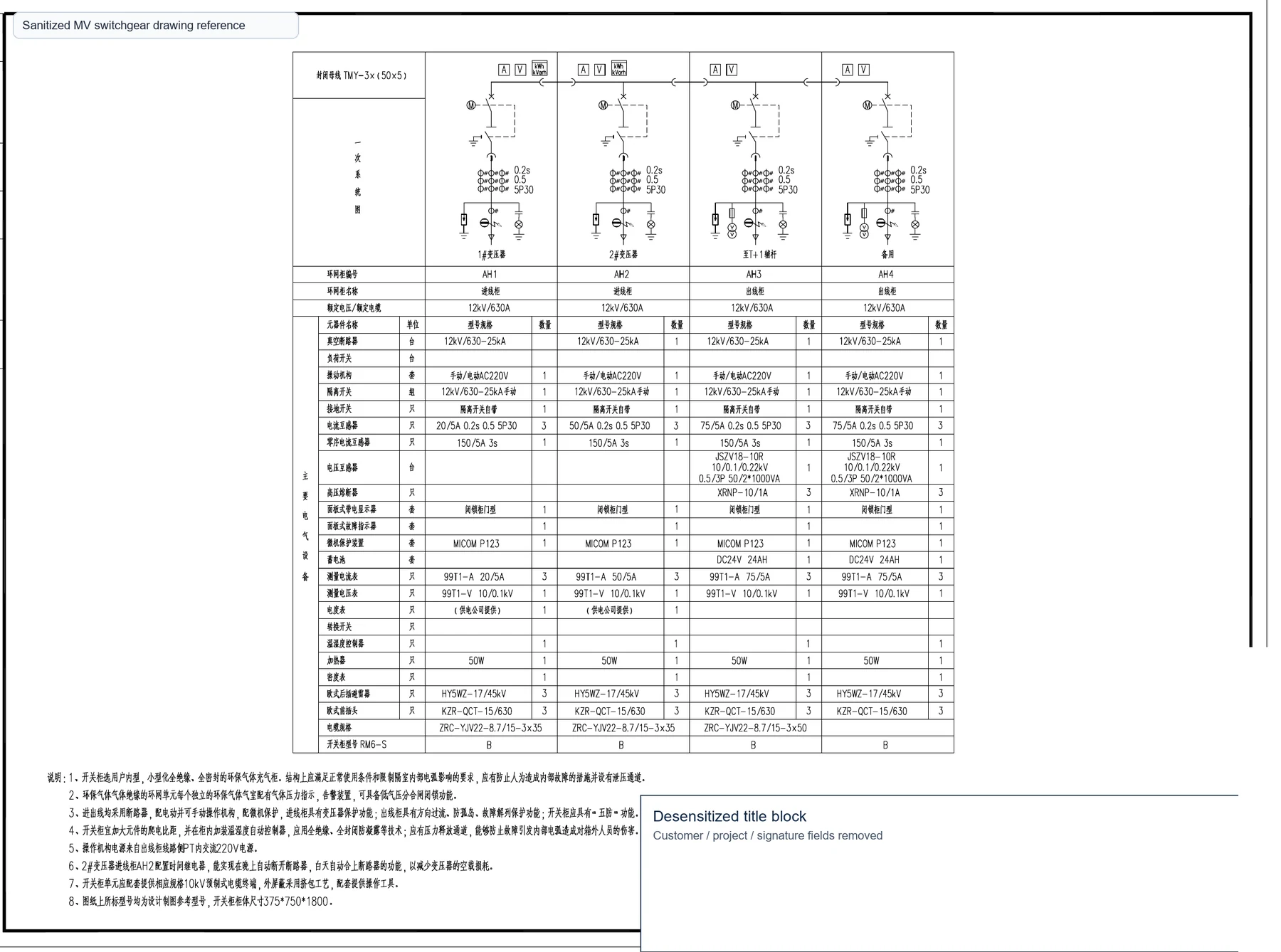
Engineering References are technical notes, not marketing pages. This reference uses a sanitized PV electrical drawing excerpt to explain common design logic for distributed solar power projects.
Search Intent
- distributed solar PV electrical design guide
- PV transformer and switchgear selection
- solar farm single-line diagram reference
- PV project RFQ checklist
Design Objectives
A distributed solar PV electrical design should achieve:
- Reliable grid connection from inverter output to utility or plant distribution network.
- Stable inverter operation under real site voltage and loading conditions.
- Safe protection coordination between inverter, transformer and MV switchgear.
- Future capacity expansion where roof, land or interconnection capacity allows.
- Compliance with local utility interconnection and IEC equipment requirements.
Engineering Summary
Distributed PV projects require more than PV modules and inverters. The AC collection system, step-up transformer, switchgear, metering, protection and grid interface must be coordinated as one electrical system.
This reference focuses on the distribution equipment side: how inverter output is grouped, how transformer capacity is selected, when RMU or switchgear is used, and what information is needed before equipment quotation.
Typical Engineering Workflow
- PV capacity: confirm DC capacity, AC output and project expansion plan.
- Inverter selection: define inverter quantity, output voltage and AC grouping.
- AC collection: plan combiner panels, feeder routing and cable size.
- Transformer selection: select step-up transformer capacity, impedance and installation type.
- MV switchgear: define ring main unit, KYN28A switchgear or utility interface scheme.
- Protection coordination: confirm CT/PT, relay, surge protection and earthing requirements.
- Metering: align revenue meter, plant meter and utility interconnection requirements.
- Grid connection: verify voltage, protection and documentation before commissioning.
- Commissioning: test insulation, phase sequence, relay function and inverter synchronization.
System Architecture
A typical distributed PV electrical architecture includes PV arrays, inverters, AC combiner or feeder panels, step-up transformer, medium-voltage switchgear or RMU, metering cabinet and grid interconnection point.
Small commercial PV systems may connect at low voltage. Larger distributed PV projects often require a transformer and MV interface to reduce current, voltage drop and feeder loss.
Equipment Selection
| Equipment | Typical Role | RFQ Information Needed |
|---|---|---|
| SCB13 dry-type transformer | Indoor or building-connected PV step-up transformer where fire safety and indoor installation are important. | AC capacity, primary/secondary voltage, impedance, vector group, enclosure and temperature control. |
| S22-M oil-immersed transformer | Outdoor step-up transformer for PV plants or industrial solar projects. | Capacity, voltage, cooling, accessories, altitude and outdoor environment. |
| YB prefabricated substation | Package transformer station for PV collection and grid connection. | Transformer capacity, MV scheme, LV feeders, enclosure type and site layout. |
| Ring main unit | Compact MV switching for loop or radial PV connection. | Rated voltage, feeder quantity, switch type, protection function and cable interface. |
| KYN28A MV switchgear | Metal-clad MV switchgear for larger PV connection or utility interface. | Voltage, current, short-circuit level, relay function, CT/PT and metering scheme. |
| Solar and power cables | Connect inverter output, transformer and MV/LV distribution sections. | Cable size, voltage grade, laying method, route length and termination requirements. |
Engineering Considerations
- Transformer capacity: inverter AC output, loading strategy and expansion plan should be reviewed together.
- Voltage level: LV or MV connection depends on project size, cable distance, utility rule and loss target.
- Protection: inverter behavior, transformer protection and grid protection settings must coordinate.
- Metering: revenue metering and plant monitoring may require different CT/PT accuracy classes.
- Surge protection: PV projects need appropriate surge protection due to outdoor equipment exposure.
- Future expansion: cabinet space, transformer margin and feeder arrangement can reduce future reconstruction.
Common Engineering Mistakes
- Using transformer capacity equal to inverter capacity without checking loading, temperature and expansion assumptions.
- Ignoring future PV expansion even when site area or interconnection capacity allows growth.
- Improper CT ratio or accuracy class selection for metering and protection.
- Insufficient surge protection or unclear earthing arrangement.
- No spare feeder capacity for future inverter groups.
- Requesting quotation without inverter output voltage, AC capacity or utility interconnection voltage.
Engineering Lessons
Many distributed PV projects expand within two to three years. Leaving spare transformer capacity and feeder positions during the first construction phase usually reduces future reconstruction costs.
Another lesson is that metering and utility protection should be discussed early. Late changes to CT/PT, relay or metering cabinet requirements can delay grid connection even when the main equipment is already built.
Design Verification Checklist
- PV DC capacity and inverter AC capacity confirmed.
- Inverter output voltage and quantity confirmed.
- Utility or plant interconnection voltage confirmed.
- Transformer capacity, impedance and vector group confirmed.
- RMU or MV switchgear scheme confirmed.
- CT/PT ratio, accuracy and metering requirement confirmed.
- Surge protection and earthing requirement confirmed.
- Expansion allowance and spare feeder requirement confirmed.
Applicable Products
- SCB13 dry-type transformer
- S22-M oil-immersed transformer
- YB prefabricated substation
- RMU ring main unit
- KYN28A medium-voltage switchgear
- Power cables and solar cables
FAQ
How is transformer capacity selected for a PV project?
Capacity is selected from inverter AC output, expected loading, temperature, expansion plan, utility requirement and transformer thermal margin. It should be confirmed with the EPC or utility specification.
Should RMU or metal-clad switchgear be used?
RMU is often used for compact loop or radial MV connection. Metal-clad switchgear is preferred where higher configuration flexibility, relay protection, metering or utility interface requirements are needed.
How are inverter outputs grouped?
Grouping depends on inverter rating, cable distance, voltage drop, protection arrangement and transformer input. The grouping should be shown clearly in the single-line diagram.
How is PV metering normally configured?
PV projects may require revenue metering, plant monitoring and protection metering. CT/PT ratio and accuracy class should be confirmed before switchgear or metering cabinet production.
RFQ Checklist
If the drawing is incomplete, send the available PV capacity, inverter list and interconnection voltage. The engineering team can assist with preliminary transformer and switchgear selection before quotation.
- PV DC capacity and inverter AC capacity
- Inverter quantity and output voltage
- Grid or plant connection voltage
- Transformer installation type and environment
- RMU or switchgear feeder quantity
- Metering and CT/PT requirements
- Expansion plan and site constraints
Engineering Reference Download
For PV equipment procurement, request an engineering reference matched to your inverter list, voltage level and interconnection requirement. ZY POWER can review the available system information and prepare an equipment configuration for quotation.
Send Your Specs or review solar power distribution solutions.
Download This Guide as PDF
Save this technical guide for offline reference. Includes all tables, specifications, and contact information.
Related Articles
Engineering Reference: MV/LV Switchgear Design
A technical reference for MV/LV switchgear design, feeder planning, single-line diagrams, equipment selection and RFQ preparation.
Engineering Reference: Industrial EV Charging Power Distribution
A technical reference for industrial EV charging power distribution, transformer sizing, LV feeder design, protection coordination and RFQ preparation.