Critical-load boundary
Separate IT load, cooling, life-safety systems, controls and non-critical services. State allowable interruption and transfer behaviour for each group.
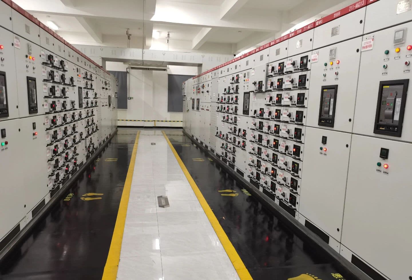
Data centre power infrastructure
Configure the electrical package from the approved load schedule, redundancy objective, operating scenarios and destination requirements. Equipment ratings and evidence remain project-specific.
Design basis
Availability terminology does not prescribe one universal transformer arrangement. The owner and design engineer must define the required behaviour, then verify it through studies, drawings and commissioning.
Separate IT load, cooling, life-safety systems, controls and non-critical services. State allowable interruption and transfer behaviour for each group.
Show utility, generator, UPS and bypass paths on the single-line diagram. Include maintenance states and credible single failures defined by the owner.
Confirm voltage, frequency, short-circuit level, load steps, harmonic spectrum, transformer inrush, earthing and selective-protection requirements.
Coordinate losses, ventilation, ambient temperature, enclosure, noise, cable access, monitoring, fire strategy and future expansion blocks.
Coordinated equipment scope
Transformer, switchgear, UPS and control interfaces should be checked together against normal, maintenance and fault scenarios.
Select rating, voltage ratio, impedance, vector group, losses, temperature rise, enclosure and monitoring from the approved load and room study.
Review SCB13 seriesCoordinate bus ratings, internal arrangement, protection relays, metering, transfer logic, cable interfaces and maintainability with the system architecture.
Review switchgearDefine UPS, generator, BMS or DCIM, auxiliary supply, communication, alarm, remote-trip and commissioning interfaces before the panel drawings are approved.
Review system scopeZY POWER can prepare equipment data, drawings and an agreed test package from the project inputs. Final facility availability classification, local approval and system performance remain with the owner and responsible design team.
Critical power design basis
A data-centre label does not define one transformer or switchgear arrangement. The owner and design team must state the critical-load boundary, maintenance philosophy, fault response and expansion plan before equipment ratings and redundancy can be selected.
Separate IT, cooling, life-safety and auxiliary loads. Record UPS input characteristics, harmonics, transformer inrush, starting duty, power factor, diversity and future capacity blocks.
Trace each normal, maintenance and contingency path from utility or generator to the critical load. Coordinate transformer impedance, bus ratings, selective protection, transfer logic and earthing.
Confirm room temperature, ventilation, enclosure, losses, noise limits, monitoring points and alarm interfaces. FAT and commissioning records should prove the contracted configuration, not a generic catalogue example.