Solar Farm Transformer Guide
Solar Farm Transformer Overview
Solar farms require specialized step-up transformers to connect PV inverters to the grid. Common configurations include pad-mounted oil-immersed transformers (S22-M, S13-M) rated 500-5000kVA with dual-voltage taps for inverter-side harmonics.
Key Selection Factors
- Voltage ratio: 0.4kV/0.8kV (LV) to 10kV/35kV (MV)
- Cooling: ONAN for outdoor installation
- K-factor rating: For harmonic-heavy inverter output
- Standards: IEC 60076, IEEE C57, grid codes
Engineering decision guide
How to apply this topic to a real project
Apply Solar Farm Transformer Guide to the actual load profile and continuity objective of the facility. Sector labels such as hospital, data centre, solar plant or factory do not define one universal transformer arrangement; the critical loads, source configuration and operating philosophy must do that work.
Separate essential and non-essential loads, identify nonlinear or cyclic duties, and document future expansion. Coordinate utility supply, generators, UPS, storage, transfer equipment, transformers and switchgear so that each operating mode has a clear power path and protection response.
The selected architecture should show normal, maintenance and fault conditions, the accepted loss of load for each condition, equipment loading, transfer sequence, monitoring points and the evidence required before energization.
Engineering checks
- Classify loads by criticality, power quality sensitivity, starting duty and allowable interruption time.
- Confirm redundancy targets and trace every source-to-load path on the single-line diagram.
- Check harmonic, inrush, motor-starting and power-factor effects against transformer and switchgear duty.
- Coordinate local authority, utility, fire, safety and commissioning requirements for the destination project.
Records to request or retain
- Load schedule and critical-load classification
- Single-line diagram with operating scenarios
- Availability, power-quality and protection studies
- Commissioning plan and alarm matrix
References to confirm for this topic
Example architectures do not certify a tier, medical, utility or statutory outcome. The owner and project engineers must approve the final design against the destination rules and verified project data.
Related Products
Recommended Transformer Solutions for the applications covered in this guide.
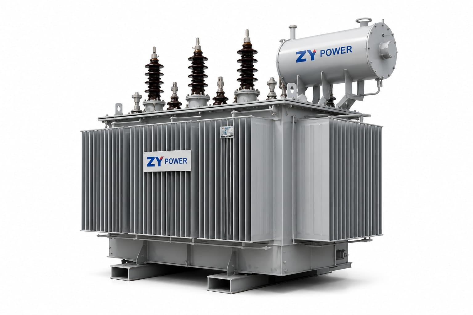
S13 Oil-Immersed Distribution Transformer
S13-500/10
S13 series three-phase oil-immersed distribution transformer with hermetically sealed corrugated tank. Rated 500kVA, primary 10kV, secondary 0.4kV. Uses a silicon steel core with low-loss oil-immersed transformer design for rural electrification, industrial distribution and utility networks.
View detailsS22 Ultra-Low Loss Oil-Immersed Transformer 500kVA
S22-500/10
S series three-phase oil-immersed distribution transformer with hermetically sealed corrugated tank. Rated 500kVA, primary 10kV, secondary 0.4kV. Features amorphous alloy core for ultra-low no-load loss, exceeding GB Class 2 efficiency. Compliant with IEC 60076 and GB 1094 standards. Outdoor installation for utility networks, rural electrification and industrial distribution.
View detailsS20 Low-Loss Oil-Immersed Transformer 630kVA
S20-630/10
S series three-phase oil-immersed distribution transformer with hermetically sealed corrugated tank. Rated 630kVA, primary 10kV, secondary 0.4kV. Optimized core design for reduced losses with competitive pricing. Compliant with IEC 60076 and GB 1094 standards. Outdoor installation for utility networks, rural electrification and industrial distribution.
View detailsNeed a Quote for This Application?
Tell us your voltage, capacity, quantity, and destination. Our engineering team will confirm the right Transformer Solutions and prepare a quotation.
Download This Guide as PDF
Save this technical guide for offline reference. Includes all tables, specifications, and contact information.